Guides, Parts & Rules
Here we’ve put our guides, recommended parts and the UK rules to help you get building your own combat robot. Use the buttons to switch between the different weight classes and our guides, suggested parts and UK rules:
General
Use the buttons to check out our general build guides, recommended parts and the UK rules:
General Guides:


These are the four main weight classes of combat robots you’ll see in the UK. At BBB we do events in ant, beetle & feather, and we’ve got guides, rules and recommended parts for all of them – use the buttons above to check them out.
BBB Guides:
From 2018 – 2023 we used to run bodgebots at our events – quick built 500g robots made out of junk for a great quick go at robot combat, we’ve kept the guide for that here as a few other places still dabble in running it!
BBB Combat Robot Basics:
Updated 13/2/24
So, you want to build a combat robot but have no idea what any of those acronyms mean or what any of these random circuit boards do? Fear not! We’ve all been there. Hopefully this guide will help you get a grasp on what you need to know.
Controlling a Robot – Transmitter and Receiver (Tx & Rx)
Arguably the most important parts of a robot are what we call the transmitter and receiver. The transmitter is the controller we hold, transmitting instructions to the robot. The receiver receives those instructions and sends them on through little 3-pin connections. You might often see these referred to as a Tx and Rx respectively. When purchasing these, make sure they can talk to each other! Different pieces of equipment run on different protocols.
We recommend using the FS-i6 Transmitter and the FS2A 4CH receiver as they are easy to get hold of and can mix and match well. A good transmitter is a great investment as one with ‘model memory’ (such as the FS-i6) can remember multiple receivers, allowing you to switch between robots extremely easily – one transmitter for all your robots!
The Brains – Electronic Speed Controllers (ESCs)
Unless you’re using very specific motors to drive your robot (servos – more on those later!) you’ll almost definitely need an Electronic Speed Controller – ESC. ESCs convert the instructions from the receiver into a voltage that gets sent onto the motors. The more you move a stick on the transmitter, the larger the voltage and therefore the more movement you will get.
Speed controllers will be labelled as ‘brushed’ or ‘brushless’. These refer to 2 different types of motor (see: Drive Motors). Often, you will also see ‘bi-directional’. This is ideal as we want to have reverse!
You will find many different options for ESCs, some may also be ‘dual channel’ – this means they take 2 channels of your receiver, meaning they drive 2 motors! Some of these have ‘mixing’ built in. Mixing is a feature it is important to have somewhere in your setup, converting your left/right (‘aileron’) and forwards/back (‘elevator’) into signals that’ll make both your motors work! You can get separate mixers or, more often, use in-built mixing on an ESC or a TX.
It’s Alive! – Drive Motors
Drive motors are what will propel your machine across the arena to victory! Commonly these will be ‘brushed’. Brushed motors are the conventional type of motor you may have once made a model of in school, with the centre coil rotating inside magnets when an electrical current is applied.
Brushless motors are similar to brushed motors, however the commutation (switching energy through different coils) is done by an electronic controller instead of by switches inside the motor. These tend to be more expensive and the need for an electronic controller means they have 3 input wires as opposed to 2.
POWER!!! – Batteries (lipos) & Battery Eliminator Circuits (BECs)
To power combat robots, many people use a battery technology known as LiPo, or Lithium Polymer. These can be volatile but when treated well are extremely useful, having a very high amount of power stored compared to their size. These will always need a suitable charger.
Receivers tend to only be able to take around 5V, which is a problem if your battery is a larger size. To combat this, we use Battery Eliminator Circuits, or more commonly, BECs. BECs take in a voltage, change it, and output another – often for our uses 5V. These are frequently built into speed controllers – worth checking before you buy a separate one!
Defending Yourself – Armour and Chassis Construction
Building a polycarbonate (ants) or HDPE (beetles) shell is an extremely viable way of building and is still used by many champion bots! 1.5mm Polycarbonate is great in ants. 10mm HDPE in beetles, 20mm HDPE in feathers for chassis walls.
3D printing has become a very common practice within antweights and increasingly within beetleweights. This allows complex shapes and shells to be designed on a device, printed, and have all internals slotted in ready for use. Common ‘filaments’ (materials to be printed from) include TPU and PLA. A higher ‘infill’ will increase the density – and potentially strength – of your print.
Weapons are, of course, the cornerstone of combat robotics. We’ll cover a few (and how you could implement them into an antweight or beetleweight) here.
Time to Attack – Weapons
Wedges
Being under your opponent gives you the chance to drive them around and put them into whatever hazard you wish, or even cause damage if you speed them into the walls! Many antweight builders add acetate sheet to the ends of their wedges to make them even ‘wedgier’!
Lifters and Grabbers
Lifters and grabbers can be achieved by using servo motors (on ants and beetles) and linear actuators (on feathers). Plug them straight into the receiver and attach your weapon of choice!
Axes
Axes can be achieved by using a brushed gearmotor (one that you may use for drive!) and a separate brushed speed controller
Spinners
Spinners are more complex. To build an effective spinner you need a brushless motor and brushless speed controller. Please consider building a different type of robot as your first robot, and even then, never test outside of a safe arena! You will most typically see vertical spinners (verts) and horizontal spinners.
At the end of the day, weapons are a very individual thing, and only you know exactly what you wish to build – if you need help getting there, ask!
Skills
Soldering
Soldering is a frequently used technique to connect wires and one you get better at with practice. Investing in a good quality soldering iron, good quality solder and watching some tutorial videos is highly recommended!
CAD/General design
Many people turn to CAD (Computer Aided Design) to assist with their machines (some easily available software including Autodesk Inventor and SketchUp), though many people also sketch panels or even design using a different CAD – Cardboard Aided Design! There is no right or wrong way to develop your machines design, so go for whatever feels natural and change as appropriate – you only learn this by trying.
General Parts:
NOTE: we are using affiliate links for some of the shops listed – any money raised goes back into funding our events and equipment! These links may be out of date and we recommend shopping around for the best deals.
General Rules:
BBB Rules:
By weight class from small to large, BBB’s build rules and other UK event organisers rulesets too:
- Ant Rules & PLANTS modifiers – 150g antweights
- Beetle Rules & Pub Modifiers – 1.5kg beetleweights
- Feather Rules & BEVs Modifiers – 13.6kg featherweights
BBB’s Competition rules and code of conduct:
- BBB Competition Rules – applies at every BBB event.
- BBB Code of Conduct & Incident Report Form – applies at every BBB event.
- Showdown Judging Criteria – applies at competitive BBB events (Brawl, Sub & Champs)
FRA Rules:
The Fighting Robots Association (FRA) have a sets of rules and codes of conduct that many UK Event Organisers follow:
- FRA Build Rules (used for beetles to heavies in the UK)
- FRA Tech Checks (used for beetles to heavies in the UK)
- FRA Code of Conduct
- FRA Competition Rules
Antweights
UK Ants are 150g in weight and sometimes have some size restrictions (see rules tab) Use the buttons to check out our build guides, recommended parts and the UK rules for ants:
Ant Guides:
Useful Ant Links:
- UK&EU Upcoming Ant Events
- BBB Ant Forum
- BBB Facebook Group
- Antweight Combat Robots Facebook Group
- Combat Robotics Facebook Group
- robotwars101.org Antweight forum
Building an Antweight using the BBB Ant Drive Kit:
Updated 5/4/24
Through this guide, we’ll hopefully get you from a pile of parts to a fully functioning circuit, or even a fighting fit machine!
Any issues or questions during the build, you can email us at bristolbotbuilders@gmail.com or message us on facebook, we’ll be happy to help.

Parts you will need:
As well as the included parts in the antweight drive kit you’ll need the following parts (we’ve linked some suggested ones):
- a 2S lipo battery to power the robot (see the list on our recommend parts page for suggestions of where to get 120-300mah)
- a lipo balance charger to charge the battery if you did not select one in the kit
- a transmitter to drive the robot if you did not select one in the kit
- and a receiver if you did not select one in the kit (make sure is compatible with your transmitter)
Tools you will need:
- Soldering Iron & solder
- Wire cutters/strippers
- Heat shrink or electrical tape
- Cross head screwdriver
- Optional: Scissors, drill, hacksaw for making a polycarbonate chassis
Circuit Aim:

Once we’ve soldered and plugged everything in, we’re aiming for a circuit that looks like the one above.
Below, you can see it in diagram form thanks to Team DSC!

Part 1: Soldering the Motors
The BBB Dual ESC comes with the connectors pre-soldered, but we still need to solder the N20 drive motors.
Firstly cut off the circled two black connectors , these are the motor outputs. You can shorten the wire a bit if you like to save a bit of weight and space.

When soldering check the back of the motors, look for the little plus symbol by one of the N20 motor tabs.

It’s worth soldering the plus side motor tab to the ESC’s motor output red wires on both N20s – this means they’ll spin the same direction when we want them to!
Strip a bit of wire insulation off the end of each of the four wires and solder each pair of red and black wires to the tabs on the N20 motors – make sure it’s the correct two wires per motor – one pair is labelled M1 and the other M2 on the circuit board.

Part 2: Soldering the Switch
This is optional but it’s good practice to have a method for turning your robot on or off apart from unplugging the battery.
It’s only a requirement to have a switch if your antweight has a spinning weapon.
Firstly cut the circled red wire but leave the black wire as is.

Strip a bit of wire insulation off each side of the red wire and solder one end to an outer pin and the other end to the middle pin of the switch. Use heat shrink or electrical tape to cover the pins and exposed wire.

Part 3: The Transmitter
For robot combat we typically use a ‘mode 2’ transmitter, which means the stick directions are labelled as you see below.

If you’ve got a mode 1 transmitter the only difference is the Throttle and Elevator sticks are swapped.
In Robot Combat the typical transmitter setup is using:
- Elevator (up/down on right stick) for robot’s drive forwards/backwards
- Aileron (left/right on right stick) for robot’s drive left/right
- Throttle (up/down on left stick) for robot’s weapon control.
You can set up to drive your robot however you like, but we’ll use this layout in this guide.
Turn on the transmitter and select the model slot you want to use for this receiver / bot by doing the following
(for FS-i6, check your manual for your transmitter):
- Press and hold OK button to see System Setup Menu. Press OK button.
- Press UP/DOWN buttons to select Model Select and press OK button.
- Press UP/DOWN buttons to select the model you want to use.
- Press and hold CANCEL button to load model.
- Now turn off transmitter.
Part 4: The Receiver
When your receiver and transmitter are connected if you press up on the elevator stick of the transmitter, the receiver will send that signal out of the elevator pin.

Above is the pinout for the receiver that can be included in the kit.
You’ll need to find the following pins on your receiver:
- positive (+ve) – usually red wires
- ground (GND) – usually brown or black wires
- signals (PWM) – usually yellow, green or white wires.
4 signals we typically use on receivers that match up to the sticks on the transmitter diagram (above):- Throttle (THR)
- Aileron (AIL)
- Elevator (ELE)
- Rudder (RUD)
Please note: With the Flysky FS2A receiver if you ordered it unsoldered you can either chop off the motor servo connectors below and solder the wires directly to the pinholes – we like this method for space saving and less soldering! – or you can solder the included receiver pins on to the receiver (picture below) and plug in the servo connectors. Ignore this bit and skip to step 5 if you’ve got a soldered receiver.

Part 5: Connecting the Dual ESC to the Receiver
Circled below are ‘servo connectors’ which connect the the Dual ESC signal inputs to the receiver as well as provide the receiver with power (using the Dual ESC’s built in BEC – this reduces your 2S lipo voltage (8.4V at max) to 5V to protect the receiver and low powered servos from damage)

- On one servo connector:
- white wire drives left/right on the motors
- red wire provides the positive rail of the BEC at 5V (+VE)
- black wire provides ground (GND)
- Separate yellow connector: drives forwards/backwards on the motors.
In the picture below we have how we’d connect up the flysky receiver:

- white wire (left/right on the motors) plugged in to channel 1 of the flysky receiver which by default on a FlySky FS-i6 transmitter is left/right on the right stick (AIL) On the same connector the red wire connects to +VE and black wire to GND (as the BEC) powering our receiver.
- yellow wire (forwards/backwards on the motors) plugged in to channel 2 which is up/down on the right stick (ELE) .
Double check you’ve connected your receiver up correctly, each brand will have a different layout – you want white wire to AIL, red to postive, black to ground and yellow wire to ELE.
Part 6: Binding the Receiver
Firstly plug your lipo into the red JST connector circled below, and switch on your circuit.

The following steps will be specific to the FS2A receiver and FS-i6 transmitter available with the kit – if you have other equipment, follow the manuals given.

- Hold down the bind button on the receiver whilst turning it on with the switch. The blue light should be flashing rapidly, meaning it’s in bind mode.
- Hold down the bind button on the transmitter while turning it on. You will see ‘binding’ on the screen
- When the receiver is flashing slowly turn the transmitter off and on again.
- You should see the blue light on the receiver go solid.
- Now if you move the right stick up/down left/right the motors should move. You have bound the receiver to the transmitter! If not check through the instructions again. Switch off the circuit.
If all has gone to plan you have bound your receiver to your transmitter! You can now waggle the right stick and you should see both motors moving. If one or neither are moving then double check your connections with the steps above.
Part 7: Failsafing
Failsafing is when your transmitter is turned off your robot’s drive and weapon will stop. This is an important safety feature. Check the manual for your transmitter and receiver if you don’t have the following set up.
Failsafing on Flysky FS2A receiver (July 2022 and newer models – see below for how to check):
You can set the failsafe on the transmitter – you must set each channel individually. Example for FS-i6:
Good video here. With your robot on, go to Menu > System Menu > RX setup > Failsafe

- Turn on failsafes for the channels you need – in this example: Channel 1 & 2 for drive are set near middle and Channel 3 in this case is set low for spin up on throttle.
- Once you’ve set them up hold down CANCEL button to save.
- Test your failsafes are working (turn off transmitter)
The “all channels” failsafe in the menu will not work for this receiver.
Failsafing on Flysky FS2A receiver (pre July 2022 models – see below for how to check):
- Turn on both your receiver and transmitter.
- Set your transmitter’s right stick to the middle and push the left stick to the bottom.
- Hold the bind button on the receiver, the blue light will flash quickly several times then go solid. Note: this is just the failsafe for this model of receiver, if you have a different one, failsafe setup may be different. There’s a failsafe option in the transmitter menu too.
New and old versions of flysky receiver
New style have a larger square chip vs smaller rectangular on old:

Part 8: Building a Basic Chassis
At this point it’s a good time to build a chassis – first attach the wheels and motor mounts to the motors. If you’ve ordered some polycarbonate sheet, you can make a chassis like the one on the below by Harry.

To do this, cut a baseplate out of the sheet using scissors. Make holes in the polycarbonate for the mounting points. Screw the motor mounts down into the polycarbonate. Then add some sides, and maybe a wedge! Cable ties and small screws and nuts (M2, M3) are your friend! You could prototype the chassis first with card or cardboard then trace that on to the polycarbonate to cut out for your final chassis.
Alternatively many antweights are 3D printed – if you own a 3D printer or can access one (schools, universities, local libraries and hackspaces are a good place to check) you can print out a chassis! There’s lots of examples on thingiverse (make sure they’re ones that are UK sized – 150g in weight. American ones are 1lb) but you can also design one using CAD software!
Part 9: Adjusting Drive on the Transmitter
Now you’ve got a platform to test the drive! Does the right stick drive the robot as you’d expect? If not here’s some things to check:
- Is forwards on the stick turning the robot left or right instead?
- Then check your receiver connections – you’ve probably got ELE and AIL the wrong way round
- Is left on the stick dring the robot forwards or backwards instead?
- Then check your receiver connections – you’ve probably got ELE and AIL the wrong way round
- Is forwards on the stick driving the robot backwards?
- You want to reverse Elevon:
- Hold OK, press DOWN and then OK to select FUNCTIONS SETUP
- Press OK to select REVERSE
- Press OK to select CH2 (ELE) and press UP to reverse it.
- Hold down CANCEL button to save.
- You want to reverse Elevon:
- If left on the stick turning the robot right?
- You want to reverse Aileron:
- Hold OK, press DOWN and then OK to select FUNCTIONS SETUP
- Press OK to select REVERSE
- Make sure you’ve got CH 1 selected (AIL) and press UP to reverse it.
- Hold down CANCEL button to save.
- You want to reverse Aileron:
Hopefully after this you’ve got a driving robot – with the stick behaving as you’d expect!
Part 10: Adding a Weapon!
If you’ve picked up a servo, this can be plugged straight into the receiver. We want to use throttle (left stick up / down) for the weapon, so on the flysky receiver we’d plug it in to channel 3, making sure black goes to ground, red to positive, and yellow/white to signal, same as the ESC.
If you test out this with the power on you can see that up/down on the left stick of your transmitter will move the servo from one end of it’s travel to the other.
Servos lend themselves well for a lifter or a grabber weapon. You can see an example of a lifter robot in Part 9. Here’s an example of how to use the servo for a grabber robot Spirit of Razer made by Michael:

To add some more power to your servo – if it supports 8.4V (the maximum charge of a 2S lipo) – which servos from BBB shop do – you can wire it in line with the battery to get some extra torque, here’s the wiring diagram:

And Done!
That’s pretty much all the steps to making a driving chassis! We hope you enjoy your building and competing experience. After your first bot, why not try extending your abilities? Perhaps designing a chassis to be 3D printed could be in your wheelhouse, or trying a different sort of weapon to add some variety.
Any questions please email us at bristolbotbuilders@gmail.com or post in the facebook group!
Thanks for reading 🙂
– Craig & Joe
Ant Parts:
NOTE: we are using affiliate links for some of the shops listed – any money raised goes back into funding our events and equipment! These links may be out of date and we recommend shopping around for the best deals.
Ant Rules:
Antweight World Series (AWS) v4.3 Robot Rules (Section 2):
2a) Weight limit: Roller: 150g, Non-Roller (shufflers, walkers, hovercrafts): 225g
2b) Size limit: robots must fit completely inside a four inch (101.6mm) cube of the following dimensions, it does not have to sit flat on the floor of the cube. Robots may only expand from their size limit once a fight has begun, and only if the expansion is instigated by remote control (i.e. not just by being springy).
Note: Size limits vary per event, see organisers below – For BBB, 200mm starting square (see below).
2c) Robots must have an externally accessible way of being shut down (e.g. a power switch, removable link or battery plug) that can be operated without tools.
2d) Radios may use the following frequencies: 27 MHz, 40 MHz, 418 MHz, 433-434 MHz, 868 MHz and 2.45 GHz. All radios must comply with all relevant rules and regulations.
2e) For safety purposes, all weaponry must have the capability of being deactivated by remote control.
2f) Failsafe – The robot shall cease all motion when the controlling transmitter is switched off.
2g) The following weapon types are not permitted:
- Glue or sticky pad weapons
- Fluid based weapons (treacle guns, etc.)
- String or entanglement weapons
- Flame based weapons
- The use of electricity as a weapon
- Explosive weapons
- Rotating weapons that may shatter (as opposed to breaking off)
- Magnetic/inductive systems
2h) Any system involving the use of pressurised gas or liquid is limited to 100 p.s.i. (7 Bar).
2i) Weapons are not permitted to deliberately detach completely from the robot, but may be partially separated as long as it is connected by a tether of no more than 3 feet (914mm). The tether may not be used as an entanglement weapon.
2j) All sharp edges must have protective covers outside the arena. All protective covers are to be made clearly visible
2k) Batteries must not contain liquid acid, or electrolyte, or exceed a maximum of 24 volts.
BBB Ant Rules:
BBB typically runs 1v1 full combat ants and 2v2 (doubles) plastic ants (PLANTS) at our events, these follow the above rules with a few modifiers:
BBB Antweight Build Rules – April 2023:
Antweight World Series robot rules (above) apply apart from the four inch cube size limit. Instead the whole robot must start within a 200x200mm square on the arena floor with no overhangs. Cluster bots wider than 200mm must start stacked. BBB Competition rules apply.
BBB PLANTS Build Rules – April 2024:
BBB PLANTS (plastic ants) are a 2v2 (doubles) antweight ruleset, legal at BBB pub-based events. The class is designed to encourage newcomers into destructive fights while also allowing more flamboyant designs for seasoned builders. Antweight World Series robot rules (above) apply apart from the following modifiers:
Whole robot must start within a 200x200mm square on the arena floor with no overhangs. Cluster bots wider than 200mm must start stacked.
Active weapon required – thwackbots are permitted. Sit & spin / flail bots are not considered active weapons.
Plastic chassis & weapons materials only. No metals except for fixings, electronics, motors. Check the list below if in doubt:
– Yes: PLA, ABS, Nylon, TPU, Polycarbonate, HDPE, rubber etc.
– No: Metals, NylonX, Onyx, Carbon-fiber, kevlar, fiberglass etc.
No acetate or similar flexible thin material acting to eradicate ground clearance or slide under opponents. All entries are at BBBs discretion and these rules are subject to change. Please consult us in advance if you have queries. BBB Competition rules apply.
Other UK Antweight Rulesets & Event Organisers:
Antweight World Series Rules (above):
– Ran at Antweight World Series, BotFest and Ant Freeze events (with 4″ cube size limit)
– Ran at Robodojo, ORCS and Rock & Robots (with no size limit)
Infosec Ruleset – Ran at Infosec Battlebots (150mm square size limit, 200g weight limit)
SCAR Ant Ruleset – Ran at SCAR (no size limit)
Sheffield modified AWS ruleset – Ran at Sheffield Roboteers Society (150mm square size limit)
Beetleweights
UK Beetles are 1.5kg in weight. Use the buttons to check out our build guides, recommended parts and the UK rules for beetles:
Beetle Guides:
Useful Beetle Links:
- UK&EU Upcoming Beetle Events
- BBB Beetle Forum
- BBB Facebook Group
- Beetleweight Robot Combat Facebook Group
- Combat Robotics Facebook Group
The History of Snappy:
Craig’s beetle build from 2014-2020, showing what’s involved in beetles.
Building a Basic Beetleweight with BBB:
Updated 4/4/24
This guide is intended as a start point for those who haven’t built beetleweights – or even robots in general – before. If you have any questions that can’t be answered by the guide, feel free to ask on the forum, in our Facebook group, or send us a message!
With that, let’s start at the very start…
What is a Beetleweight?
A UK beetleweight combat robot is a 1.5kg robot! Unlike UK antweights, there are no size restrictions, and unlike US beetleweights they have a slightly larger weight limit at 1.5kg instead of 3lb / 1.36kg. Beetleweights have only been a significant weight class in the UK since around 2014. Check out our rules page for more info on the rules we run.
We love beetles as we think they’re the ideal weight class for big destruction, great fights and meaty hits at a “reasonably” low cost, and in a (usually) easy to transport form factor. It’s also one of the easiest classes to try new ideas in, and so many are still untouched!
So… What tools do I need?
You can kind of consider the following list the minimum tooling you’re likely to need for the most basic of beetleweights.
- A Soldering iron and solder
- Electrical tape and/or Heat shrink
- A Drill and some bits.
- Screwdriver, with various bits.
- Hex keys
- A Junior hacksaw, maybe a Jigsaw if you gotta go fast
- If you have access to a bandsaw at a local hackspace or similar it cuts HDPE like a dream!
- A small workbench, vice or something to clamp HDPE sheets on to!
What components go into a basic beetleweight?
You can check out our recommended parts list in the tab above, but to cut everything to it’s basics and briefly overview the purpose…
| LiPo Battery For a standard beetle, a 3S LiPo (Lithium Polymer) battery around the 650-850mAh (milliamp hour) capacity should do you fine. 4S is often an option too, but we recommend starting with 3S. |  |
| Receiver (Rx) / Transmitter (Tx) What you use to control your robot, and the component that… receives those signals! Get a nice pairing that failsafes and has mixing – more on that later. We recommend the FS-i6 transmitter, which comes with a receiver. |  |
| Drive Motors We love using our 22mm Brushed motors for drive on 3 or 4S, they’re a great option for most robots. There’s also lots of brushless drive options which are great for a later upgrade or a second build. |  |
| Connectors For ease, it’s common to find out what connector your LiPo uses and buy a bunch of both male and female of these – You’ll need one to connect the battery to your robot anyway. Any spares you can use for things like removable links. Commonly used connectors mainly consist of XT30s and XT60s. | 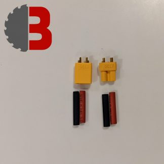 |
| BECs Most beetles run on 3S lipo (or higher) batteries which is 3 cells or 11.1 volts. The difference between this and ants is that components like the receiver and most servos don’t run at this higher voltage. The way we handle this is lowering the voltage with a ‘UBEC’ to 5V. UBEC stands for Universal Battery elimination circuit – just means it’s converting the lipo battery voltage to a lower voltage. | 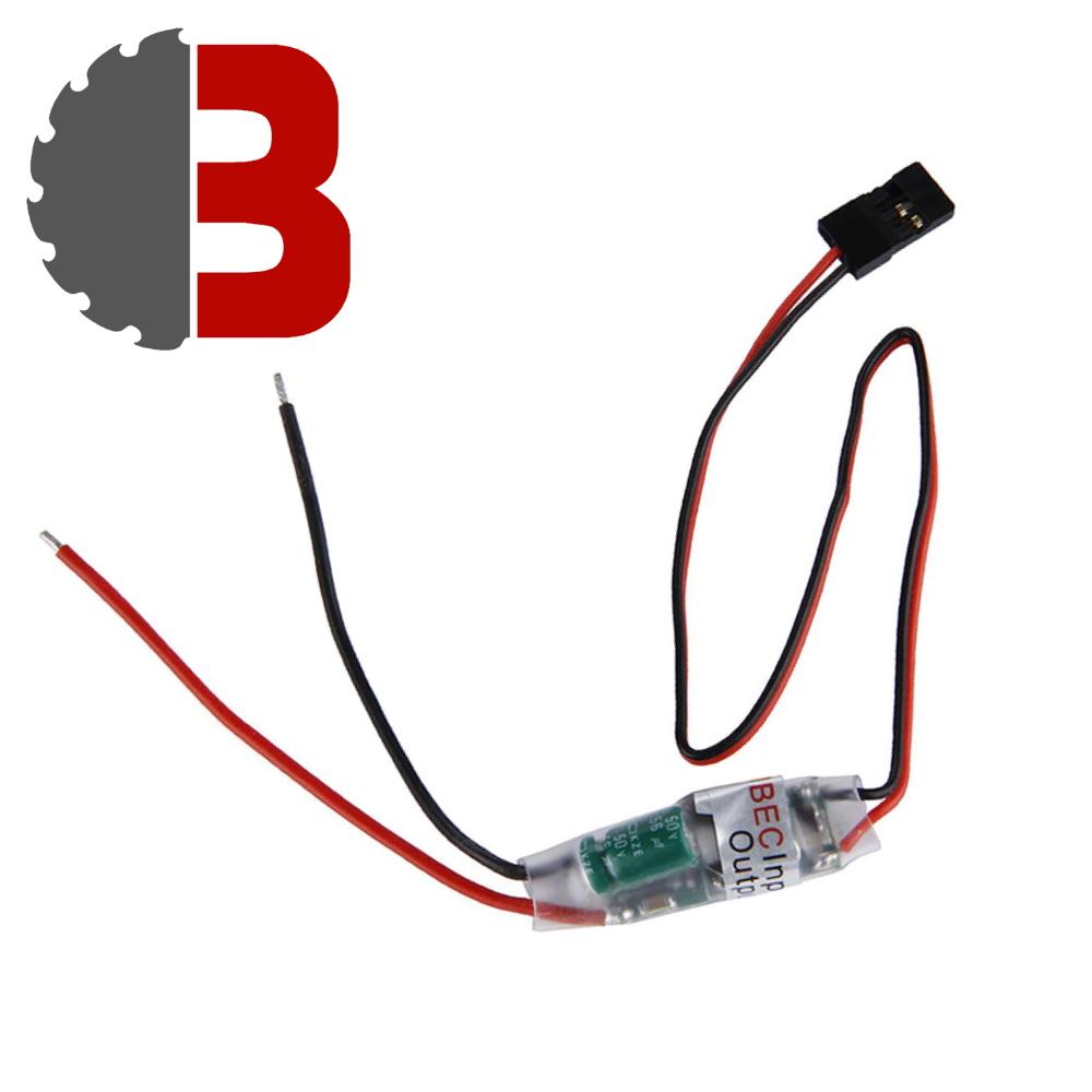 |
| Speed controllers (ESCs) These take input from your receiver and output speed and direction to your motor! We stock our own single channel (1 per side) and dual channel (controls both sides) in the store. The examples below use single channel ESCs. | 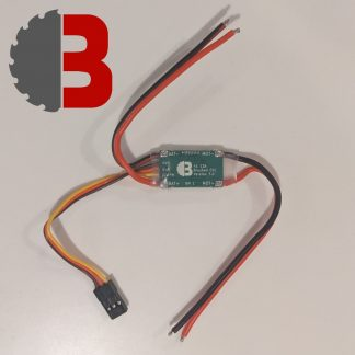 |
How do I connect them together?
The main components you’ll be connecting directly to your LiPo will be your ESCs and BEC.
Speed controllers (ESCs) to drive the motors – one per drive side so two of these! – you can see labelled on the green PCB (chip) where the wires are meant to connect to below:

BECs – to take down the voltage to a safe level for the receiver. We only have 1 receiver so we only need 1 BEC. Some people may also run a BEC to lower their battery voltage for components like servos.

So here’s the two ESCs, the BEC and the LED connected up to power from the lipo battery:

Note that there is currently no removable link – read on before soldering up!
Breaking Out:
You may notice we have multiple components being wired from 1 battery connector. If that seems daunting, the wonderful Dave Weston has you covered with this tutorial for breakout cables.


If this looks a bit tricky if you’re new at soldering, BBB sell these pre-made for an XT30 and for an XT60 connector.
Removable Links
Removable Links are, along with a power light, an essential safety component. These need to be accessible externally of the robot without any tools. One pro tip is to use appropriately rated fuse wire to connect your link terminals, as a fuse is another UK essential!

Below are 2 placements you could choose for your removable link – notice that it is always wired on the red positive wire.
Check out this excellent guide from Eoin of Team Barróg on link placement and securing your link well in fights!


Full Drive Circuit:
With our removable link installed, we’re ready to connect our motors. When soldering the connector to your LiPo, make sure the polarities match – black to black, red to red.

Note about BECs:
BECs (battery eliminator circuits) power your receiver at a lower voltage than your battery.
Do not use more than one BEC at a time – if your drive or weapon ESCs have a red servo wire (the wires that you plug in to the receiver) then unplug/cut the red servo wire on all but one ESC if you wish to power your receiver with a built in BEC.
If you’re powering a servo or other higher current components use an external BEC (like the circuit pictured above) and disconnect all other BECs.
When connecting your receiver, it’s important to connect wires in the right orientation or you may break the receiver. Check the documentation for your receiver, but the commonly used FS2A is seen here.
The row of pins furthest from the main board are for the black ground wire, while the closest are for the usually white signal wire.
If you need more details, we have a whole binding and mixing guide here
Weapons:
Time for the fun bit. Now you’ve got a safe, driving beetle, it’s time to add a weapon. We’ll show you 3 example of how to wire those in through this section.
Servo Weapons:
A servo motor rotates in a limited range (normally 90 to 180 degrees) with lots of torque – great for grabbers and lifters. We recommend at least 30kg servos for enough torque for beetles.
You can extend the range it rotates with a servo extender!

Brushed Gearmotors:
Gearmotors are also a good option for a weapon – 37mm motors at higher speeds (rpm) are good for axes, and lower speeds for lifters!
You’ll need to connect them to another brushed ESC, same as the drive motors!

Brushless Motors:
Brushless motors are great for spinning very fast – and so are typically used to make spinners – horizontal, vertical, drums, saws.
You’ll need a brushless ESC to make it spin.

Making a Chassis:
Though it is becoming increasingly common to have 3D printing incorporated into builds, many top robots are still comprised mostly of a material called HDPE, or High Density Polyethylene. It’s easy to buy, robust, inexpensive and easy to work. You may even unknowingly have a block of it on your kitchen worktop in the form of a cutting board. You can screw it together tightly using woodscrews, and even cut it with basic junior hacksaws.

Common beetleweights are often comprised mostly of 5mm and 10mm HDPE, using 10mm for important, structural walls and 5mm for baseplates, lids, and other armour plates. The bends in this robot were produced with a heatgun, and the panels fixed together with 4mm woodscrews driven into 3mm holes, ‘countersinking’ the hole to fit the screw head.
As mentioned, HDPE is super easy to work with, with even the thicker stuff workable by hand. Other tools like jigsaws or bandsaws just speed up the process, while you can also use heat guns to produce bends. To make your cuts more precise, you could ‘draw’ the cuts on first using rulers and Stanley knives (they’re sharp be careful <3) and recheck all the measurements to ensure everything is even and square.
The Ground Game:
The battle for low ground has developed a lot over the years in beetleweights. While many robots found and still may find success with a flat wedge front as seen with robots like Snappy above, and would still be recommended for those less confident (5mm HDPE with a nice air gap behind is your friend!), you may wish to investigate adding forks to your robot. You can see 2 examples from Bish Bash Bosh and Aggro Wobba below.


Wheels:
Almost there!
In years past, beetle fights would often end due to wheels literally falling off of their own accord, but with so many great options now available this is increasingly rare.
| Repeat Gold Eco Hubs have two M4 grub screws for extra strength to hold on to the shaft, while the end plate is attached with two M3 8mm screws. The front plate has 3mm holes for the option to attach a pulley to the inside of the hub. These are designed to attach foam wheels, such as the ones produced by Fingertech. |  |
| Fingertech foam wheels are excellent at absorbing shock and are incredibly versatile. You can even pop a layer of liquid latex around them for that extra grip. Combine with the Gold Eco hubs above. |  |
| A common practice amongst builders is now to 3D print your own wheels, cast polyurethane onto them, and attach using an off the shelf hub such as a Pololu hub or Repeat Gold Screw Hub. This tends to be used by more experienced or confident builders and there is no problem using off the shelf options. | 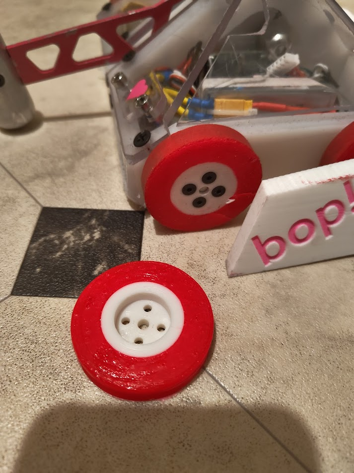 |
| Repeat Gold Screw Hubs seen here are ideal for attaching 3D printed wheels. Many older style of hubs such as Pololu tend to come with 3mm grub screws that have a habit of stripping. One thing you can therefore do is drill hubs out to 3.4mm, tap a 4mm hole, and use M4 grubscrews. Combine that with a tasty lick of threadlock (blue flavour best flavour) and you’re golden. |  |
| The other thing some do is file a slot into the output shaft. This means, as long as the grub screw is engaged, the hub physically cannot slide along the shaft and wobble off the robot. Happy days. |  |
That’s all folks!
Got this far? It’s likely you’ve made, or got everything you need, to build a successful beetleweight. Nice one!
We hope this guide helped. Join our facebook group or forum for robot discussions and hopefully see you at an event if you’re near-ish Bristol UK and want to fight some bots 🙂
Thanks for reading 🙂
– Craig & Joe
Beetle Parts:
NOTE: we are using affiliate links for some of the shops listed – any money raised goes back into funding our events and equipment! These links may be out of date and we recommend shopping around for the best deals.
Beetle Rules:
BBB’s 2024 Beetleweight Rule Summary:
While these are the general rules many beetles competitions will run, many, including BBB, will have modifiers (see below this summary for pub modifiers). If in doubt, check with your Event Organiser.
1. General Safety
1.1 Sharp Edge Protection: All Robots not in an arena or official testing area must have secure protective covers over any sharp edges. Sharp edge protection must be designed in such a way that they cannot be dislodged unintentionally.
1.2 Dedicated Locking Bars: Any moving weapon requires a locking bar that completely stops motion. The locking bar must be marked as such with a tag or tape, and not used for any other purpose than locking your robot. Steel split pins are a great option and can easily be marked or have a keyring added. A clamp is not permitted. The locking bar must not be loose. The locking location on the robot must be easily visible for the arena marshal.
1.3 Cradles: All robots not in an arena or official testing area must be on a dedicated cradle which keeps all wheels off the ground when bench testing your drive.
2. Weight
2.1 Weight Classification: Maximum 1.5kgs. No allowance is given for any margin of error. It is recommended robots are designed in such a way that excess weight can be removed easily, since scale calibration may vary. Weight includes all consumables and any part of the robot that remains inside of the arena such as gas bottles, removable link(s), and safety tethers. Locking bars, transmitters, and tools required to activate the robot that are removed from the arena are not included.
2.2 Bonus Weight: Gyro walkers (using gyroscopic forces to move) and shuffler robots (shuffling mechanisms such as rotational cam operated legs.) receive a 33% weight bonus (2kg). Walkers (each leg with 2 degrees of freedom) receive a 100% weight bonus (3kg).
2.3 Interchangeable Panels and Weapons: If used, the weight is measured with the heaviest set-up in place. All configurations need to known prior to the competition starting and spot checks may be performed at any time.
2.4 Clusterbots: As per our competition rules, cluster bots require 67% elimination by weight. Judges/Refs must know weights of each segment pre-fight. Cluster bots with both a shuffling and wheeled robots: the weight bonus to the shuffler will be applied to the remaining left over weight after deducting the wheeled robots combined weight.
3. Radio control requirements
3.1 All systems that are deemed to be ‘dangerous’ (normally the drive and weapons) must have a ‘failsafe’ device. This MUST bring the systems to a pre-set ‘off’ or ‘zero’ position if the transmitter signal experiences interference or is lost. These devices must failsafe when the receiver battery is low or if power is completely lost.
4. Electrical Power
4.1 Removable Link: The main power cut-off must be a removable link. The link must be removable without the use of tools. A key or switch is not allowed. The link must be positioned in a visible part of the robot’s bodywork, fitted away from any operating weaponry or drive, and this position must be clearly marked. The link may be fitted under a cover, but the cover must be able to be opened without the use of tools.
4.2 Power Light: Robots must have at least one surface mounted non-filament power light that is illuminated when the main link is fitted. The power light may be any colour but must be non-flashing
and in contrast with the surroundings.
5. Batteries
5.1 Safety: must be adequately protected within the body and securely fixed to minimise the chance of being punctured or coming loose during combat. In addition, packing such as high density foam is recommended to reduce the shock of impacts.
5.2 LiPos: Roboteers using LiPo batteries must provide a LiPo sack. Lithium batteries must not be left unattended at any time during the charging process. LiPo batteries showing any evidence of damage or swelling must immediately be placed a LiPo sack and removed to a safe, well-ventilated area such as outdoors.
5.3 Fusing: A fuse rated below the maximum burst discharge of the battery MUST be fitted. The
maximum burst discharge current is calculated by multiplying the C rating by the capacity. E.g. 25C 2200mAh = 55 Amp
6. Weapons
6.1 Spinning weapons: 250mph theoretical tip speed limit on all spinning weapons. Tip speed calculator here.
6.2 Restrictions: No Invisible Damage (electricity, radio jamming, electromagnetic fields), no entanglement, no shatter-able rotating blades, no untethered projectiles, no fire, no smoke or bright lights, no hazardous materials.
6.3 Unusual Weapons: If you are planning to bring a more unusual weapon type, including but not limited to pneumatic or spring loaded weapons, please contact BBB prior to signup to ensure safety.
7. Other Queries
Anything not covered by the rules above should be checked prior to the event with BBB, this includes but is not limited to the aforementioned pneumatic or spring loaded weapons. Any robot may be denied entry at tech checks if it does not comply with the above rules or anything not covered above has not been approved prior to signup.
Checklist & Competition Rules:
BBB Home Checklist – a complete list of all the safety requirements for your robot for you to check through at home before heading to an event.
BBB Competition Rules – applies at every BBB event.
Showdown Judging Criteria – applies at ‘non-pub’ BBB events (Brawl, Sub & Champs)
BBB Code of Conduct & Incident Report Form – applies at every BBB event.
BBB Pub Beetles Rule Modifiers:
Updated 13/3/24
Our good time with slightly less destructive beetles in a pub setting, non serious, no strict reffing and mob rule (crowd) judging. Only ran at specific BBB events. Four modifiers to the beetle ruleset above:
Spirit of the Pub – a good time with less destructive bots. Creative flare, theming and showmanship encouraged! All entries at BBB’s discretion.
Active weapon required – thwackbots are permitted. Sit & spin / flail bots are not considered active weapons.
Spinning weapons must be plastic or rubber.
Any unpowered wedges and forks must be:
– up to 3cm long
– OR: up to twice as long as their thinnest width
(Length measured from the nearest side of the robot)

Other UK Beetleweight Rulesets & Event Organisers:
FRA Build Rules, & Competition Regulations + 250mph theoretical tip speed limit (Tip speed calculator here) – Ran at Battle in the Burgh, Robodojo, Robot Rebellion and many others. Check with the event organiser for any modifiers.
Mersyside Competition Rules – Ran at Merseyside Robot Fighting
SCAR Beetle Ruleset – Ran at SCAR
Featherweights
UK Feathers are 13.6kg (30lb) in weight. Use the buttons to check out our build guides, recommended parts and the UK rules for feathers:
Feather Guides:
Useful Feather Links:
- UK&EU Upcoming Feather Events
- BBB Feather Forum
- BBB Facebook Group
- Featherweight Robot Combat Facebook Group
- Combat Robotics Facebook Group
- Feather focussed guide for teachers by Dan Grant
Building a Featherweight robot in a week:
Joe’s 2018 video building his first featherweight robot in a week – you may find some useful beginner strats here!
Building a Featherweight using the BBB Feather Drive Kit:
Updated 5/4/24
This guide has been written with the intention of helping anyone with a BBB Featherweight Drive Kit or similar components achieve a functioning robot!
Any issues or questions during the build, you can email us at bristolbotbuilders@gmail.com or message us on facebook, we’ll be happy to help!
What you’ll need:
As well as the parts included in the Featherweight Drive kit you will need the following:
- A 3-5S lipo battery in the 2-3000mAh range. (If this is your first feather we recommend a 3S 2200mah lipo.)
- A lipo balance charger that can charge that lipo – some suggestions here
- A transmitter (we like the Flysky i6 and it comes with a receiver)
- a receiver if you did not select one in the kit – make sure it supports your transmitter.
Tools you will need:
- 2.5mm Hex Key
- Cross head screwdriver
- Pliers or something to grip the motor shaft
- Cordless Drill to attach mounts to your robot with either:
- woodscrews, barrel nuts or screw inserts.
- Electrical Tape (optional)
- Blue Threadlock (optional)
- M5 Tap (optional)
Building a Chassis:
This section is going to be really vague as there’s tonnes of ways to build and you should do what suits you! Generally the construction of featherweights can be very similar to beetleweights, on a larger scale.
At BBB we’re huge fans of HDPE and if you want to take our approach we’d generally advise 10mm thick baseplates and 20mm thick walls as a good starting point. Woodscrews can be used to mount together these panels, but for super strong results use barrel nuts (M5 is a good size) to join walls together! We’ve not had great results using screw inserts for holding base/top plates in HDPE for full combat as they tend to tear out under spinner hits, but should be fine for non-spinner fights.

Metal chassis are much more common at featherweight than beetleweight too – both mild steel and hardox. There’s even scope for a wooden chassis if you made it really thick!
One of our findings is the 13.6kg weight leaves you with a lot more weight to play with once you’ve done the drive system, relative to beetles – if you build a basic 2WD pusher with HDPE panels mentioned above you’ll have absolutely tonnes of weight to play with (possibly even half the weight left!). As our focus with the BBB feather “BEVS” events is entertaining fights and humour, we’d really advise using that extra weight to add a weapon and decorative features!
Good ways to add a weapon is using an extra drill or two for a grabber or lifter (a bit like a servo) or a linear actuator for a more linear motion. Axes are typically powered by small electric scooter motors. We’re just giving you some inspiration, our aim is to give you the core parts to get a featherweight driving and then you add your personal spin to that! So with that, let’s get that drive kit working
Prepping the Motors:
At the heart of most featherweights are trusty drill motors – in our kit these come pre-removed from the drill casing. Drills come with an adjustable clutch that allows it the motor slip and control how much force is outputted from the gearbox. This is not what we want for a combat robot – we want all the torque, no slip!
Watch from 4:12 – 6:49 of this great video from Angus of Makers Muse fame demonstrate how to lock a clutch and how that actually works! We’re using shorter grub screws in this kit than he does so they’ll go inside the gearbox rather than stick out.
Using a 2.5mm hex key, you’ll screw the 4 included M5 grub screws into the gearbox. I do this without tapping, but some people like to use an M5 tap to cut a few threads into the start of the hole to make inserting the grub screws easier. It requires a fair amount of force to screw into the holes.
Carefully screw the grub screw down into the gearbox until you feel it just touch the output plate inside and then back it off half a turn. The grub screw will be pretty much flush with the hole.
You don’t want to be putting pressure on the output plate – you should be able to wiggle the output shaft back and forth a small amount feel the bump as the ring gear hits against the grub screws.
You’ll want to repeat this for all four grub screws in every second hole of the gearbox.


At this point it’s worth adding some electrical tape over the vent ports at the back of the motor to stop debris from getting in – they don’t need ventilation for 2 or 3 minute fights.

Mounting the Motors:
This bit is pretty simple! The front face of the gearbox sits inside the front mount and then is attached from the other side by screwing in the the two included wood screws. The back mount slides straight on behind the gearbox.

You can then attach this to the baseplate (or in the case below, top plate) of your robot. In these examples, we used 5mm woodscrews, but if you want a more reusable option you could use barrel nuts or screw inserts in the mounts.
It’s recommended to use 2 woodscrews on both the front and back mount to make sure they’re secure. The front and back mounting holes are ~61mm apart from each other, but it’s best to measure on your robot to ensure the motors are well clamped.

Attaching Wheels:
Our wheels come with a threaded hub – screw them on to the motor shaft by hand, and tighten a bit while gripping the shaft with some pliers or similar.
Then take the M5 20mm reverse threaded screw that comes with the motor and screw it by hand with a cross head screwdriver into the shaft through the hole in the wheel – note it’s reverse threaded so turn left to tighten otherwise you could damage the shaft thread! Make sure it’s fully tightened.

After a good bit of drive testing, my wheels were well attached to the motors and very difficult to remove, however if you’re having issues with wheels coming off you can use blue threadlock on the reverse threaded screw to help it stay in place. You can even do the same with the motor shaft, but bare in mind this makes removing the wheel much harder later!
A great upgrade to the wheels is to attach bike tyre with small woodscrews to add extra grip. This will wear down after a few events and need replacing to maintain good grip / pushing power! Also bare in mind this changes the diameter of your wheels quite significantly so think about ground clearance/chassis height etc!

Electronics:
This is another area that’s really similar to beetles so it’s worth starting with our beetleweight circuit diagram, made by the legendary Nick of Team DSC.
With our 18V motors we’d recommend a LiPo anywhere between 3 and 5S and somewhere in the 2000-3000mah range. We’d really recommend 3S if you’re just getting started as it’s cheap and most likely if you’ve worked with beetles your charger will work with it. If you’re feeling confident 5S will give you more speed/power on our 18V drills! Our BBB Feather ESCs will support two drills per side if you decide to do four wheel drive.
Be sure to only use one BEC in your bot to power your receiver, we generally recommend using an external BEC, but if you want to use one off your ESC of the two drive ESC – disable the other by cutting the red wire off the servo connector. If you use an external BEC, cut the red wire on all ESCs’ servo connectors in your bot, as seen below.

Receivers – Binding, Failsafing & Mixing:
We cover all of this in our transmitter guide (note: specific to our flysky receiver and FS-i6 transmitter) here are the links:
Adding a Weapon:
Active weapons are required in our BEVs ruleset, and you may just want to add one anyway! So let’s look at some common examples and implementations.
Adding a weapon – Linear Actuators:
Linear actuators or as we lovingly call them ‘linacs’ are a wonderful thing – they turn the rotation motion from a motor into a linear motion (eg up/down – see orange arrow).
They’re comprised of a brushed motor, connected to a gearbox, that goes to a lead screw that moves the rod up and down. Usefully, they have built in ‘end stops’ so when the rod hits the top or bottom the end stops are engaged, stopping the motor rotating further in that direction, preventing damage to the mechanism.
There are so many variants of a linac so here’s the specs to consider when selecting one:
Input Voltage (V) – 12V works for 3-5S featherweights
Stroke Length (mm) – how far the rod extends
Speed (mm/s) – how quickly the rod extends
Load Capacity (N) – how much force it can output
Lifters need as much load capacity as possible, grabbers can sacrifice some of this torque for more speed.
There’s plenty of linacs available on ebay UK, but if you’re looking for specific specs check out aliexpress.You can use beetle sized brushed ESCs to drive them such as a BBB ESC or vex29!

Son of Scoop (2021) by Felix
Grabber

Linac specs:
Input Voltage: 12V
Stroke Length: 50mm
Speed: 45mm/s
Load Capacity: 200N
Fry Cook (2019) by Rob
Lifter

Linac specs:
Input Voltage: 12V
Stroke Length: 150mm
Speed: 14mm/s
Load Capacity: 1000N
Crabsolutely Clawful (2018) by Joe
Horizontal Claws

Linac specs:
Input Voltage: 12V
Stroke Length: 50mm
Speed: 45mm/s
Load Capacity: 200N
First build video for this bot here. Brushless linac mod here.
Eoin’s Four-Bar Lifter (2020)
Lifter

Linac specs:
Input Voltage: 18V
Stroke Length: 50mm
Speed: 37mm/s
Load Capacity: 2300N
Adding a weapon – Scooter Motors:
More beans I hear you cry? We can give you more beans! Check out scooter motors, nicknamed ‘scooties’
These are large chunky brushed motors, often come with a built in gearbox with plenty of torque. Also typically come with a sprocket on the output shaft for attaching some chain reduction to your weapon for powerful hammers or lifters! Plenty of options on ebay.
Specs to consider:
Input Voltage (V): 24V typically with 5-6S lipo
Power (W): expected torque (250-350W is standard)
Gearbox / No Gearbox, number of sprocket teeth & RPM: basically what speed your weapon moves at
Chain size: T8F or 6mm. You’ll want to find a matching output sprocket with your choice of reduction.
We recommend using a beefy ESC for these such as a BBB feather ESC or Botbitz 80A.

Pizza Time (2021) by Rob
Lifter


24V 350W scooter motor with ~10:1 gearbox
BTR 50A ESC on 5S
6mm ~5:1 Chain Reduction
More about Pizza Time on Rob’s page here!
Hamish the Highland Coo (2021) by Dom
Hammer


24V 350W scooter motor (no gearbox)
~7:1 dual stage T8F chain reduction, 8mm sprockets
5S lipo, BBB Feather ESC
Single stage chain mechs for axes are pretty common in feathers normally 5, 6 or 7:1 reduction.
That’s pretty much all the steps to making a driving chassis! Any questions please email us at bristolbotbuilders@gmail.com or post in the facebook group!
Thanks for reading 🙂
– Craig & Joe
Feather Parts:
NOTE: we are using affiliate links for some of the shops listed – any money raised goes back into funding our events and equipment! These links may be out of date and we recommend shopping around for the best deals.
Feather Rules:
BBB’s 2024 Featherweight Rule Summary:
While these are the general rules many featherweight competitions will run, many, including BBB, will have modifiers (see below this summary for BEVs modifiers). If in doubt, check with your Event Organiser.
1. General Safety
1.1 Sharp Edge Protection: All Robots not in an arena or official testing area must have secure protective covers over any sharp edges. Sharp edge protection must be designed in such a way that they cannot be dislodged unintentionally.
1.2 Dedicated Locking Bars: Any moving weapon requires a locking bar that completely stops motion. The locking bar must be marked as such with a tag or tape, and not used for any other purpose than locking your robot. Steel split pins are a great option and can easily be marked or have a keyring added. A clamp is not permitted. The locking bar must not be loose. The locking location on the robot must be easily visible for the arena marshal.
1.3 Cradles: All robots not in an arena or official testing area must be on a dedicated cradle which keeps all wheels off the ground when bench testing your drive.
2. Weight
2.1 Weight Classification: Maximum 13.6kgs. No allowance is given for any margin of error. It is recommended robots are designed in such a way that excess weight can be removed easily, since scale calibration may vary. Weight includes all consumables and any part of the robot that remains inside of the arena such as gas bottles, removable link(s), and safety tethers. Locking bars, transmitters, and tools required to activate the robot that are removed from the arena are not included.
2.2 Bonus Weight: Shuffler robots (shuffling mechanisms such as rotational cam operated legs.) receive a 50% weight bonus (20.4kg). Walkers (each leg with 2 degrees of freedom) receive a 100% weight bonus (27.2kg).
2.3 Interchangeable Panels and Weapons: If used, the weight is measured with the heaviest set-up in place. All configurations need to known prior to the competition starting and spot checks may be performed at any time.
2.4 Clusterbots: Cluster bots require 67% elimination by weight. Judges/Refs must know weights of each segment pre-fight. Cluster bots with both a shuffling and wheeled robots: the weight bonus to the shuffler will be applied to the remaining left over weight after deducting the wheeled robots combined weight.
3. Radio control requirements
3.1 All systems that are deemed to be ‘dangerous’ (normally the drive and weapons) must have a ‘failsafe’ device. This MUST bring the systems to a pre-set ‘off’ or ‘zero’ position if the transmitter signal experiences interference or is lost. These devices must failsafe when the receiver battery is low or if power is completely lost.
4. Electrical Power
4.1 Removable Link: The main power cut-off must be a removable link. The link must be removable without the use of tools. A key or switch is not allowed. The link must be positioned in a visible part of the robot’s bodywork, fitted away from any operating weaponry or drive, and this position must be clearly marked. The link may be fitted under a cover, but the cover must be able to be opened without the use of tools.
4.2 Power Light: Robots must have at least one surface mounted non-filament power light that is illuminated when the main link is fitted. The power light may be any colour but must be non-flashing
and in contrast with the surroundings.
5. Batteries
5.1 Safety: must be adequately protected within the body and securely fixed to minimise the chance of being punctured or coming loose during combat. In addition, packing such as high density foam is recommended to reduce the shock of impacts.
5.2 LiPos: Roboteers using LiPo batteries must provide a LiPo sack. Lithium batteries must not be left unattended at any time during the charging process. LiPo batteries showing any evidence of damage or swelling must immediately be placed a LiPo sack and removed to a safe, well-ventilated area such as outdoors.
5.3 Fusing: A fuse rated below the maximum burst discharge of the battery MUST be fitted. The
maximum burst discharge current is calculated by multiplying the C rating by the capacity. E.g. 25C 2200mAh = 55 Amp
6. Weapons
6.1 Spinning weapons: 250mph theoretical tip speed limit on all spinning weapons. Tip speed calculator here.
6.2 Restrictions: No Invisible Damage (electricity, radio jamming, electromagnetic fields), no entanglement, no shatter-able rotating blades, no untethered projectiles, no heat or fire, no smoke or bright lights, no hazardous materials.
6.3 Unusual Weapons: If you are planning to bring a more unusual weapon type, including but not limited to hydraulic or spring loaded weapons, please contact your Event Organiser prior to signup to ensure safety.
7. Other Queries
Anything not covered by the rules above should be checked prior to the event with your Event Organiser, this includes but is not limited to the aforementioned pneumatic or spring loaded weapons. Any robot may be denied entry at tech checks if it does not comply with the above rules or anything not covered above has not been approved prior to signup.
Checklist & Competition Rules:
BBB Home Checklist – a complete list of all the safety requirements for your robot for you to check through at home before heading to an event.
BBB Competition Rules – applies at every BBB event.
BBB Code of Conduct & Incident Report Form – applies at every BBB event.
BBB BEVs Rule Modifiers:
Updated 1/3/24
BEVs (Bristol Fevs (Feathers)) are basically non spinner featherweights, inspired by American sportsman rules. At BEVs events you can expect a non serious competition, no strict reffing and mob rule (crowd) judging.
Feather Rules apply (above – 13.6kg, link, fuse, power light, sharp edge protection, cradle, locking bar, failsafing.) unless stated otherwise below.
Active weapon required (eg – lifter, hammer, grabber, flipper). Torque reaction (overhead) thwackbots are permitted. Sit & spin / flail bots are not considered active weapons.
No metal forks & no sharp wedges/axes – to protect our wooden floor. We recommend plastic hammers & forks. No unsticks if you’re stuck on an arena wall! We may tape up wedges or even ask you to remove forks if they are likely to damage the arena.
Max Tip Speed: 20mph or 9m/s for non-drive continuous rotation elements. Tip speed calculator here.
Pneumatic Pressure Limit: 10Bar (145psi)
Weight Bonus: We do not offer weight bonuses for BEVs.
Open Arena: Your robot must be safe for combat in a netted roof arena. Any weapon systems that may be capable of tearing off pieces of the opponent (flippers, axes, etc) must be cleared with BBB prior to competing.
The Spirit of BEVs: a good time with non destructive feathers. Creative flare, theming and showmanship encouraged! All entries are at BBBs discretion.
Other UK Featherweight Rulesets & Event Organisers:
FRA Build Rules & Competition Rules – Ran at Robodojo & Robots Live. Robodojo Full Combat has a 250mph theoretical tip speed limit (Tip speed calculator here). Robots Live do not allow spinners at their events. Check with the event organiser for any modifiers.
Robodojo Sportsman Rules 2024 – Ran at Robodojo
Disclaimer: Building, maintaining and fighting combat robots is dangerous and comes with risk that must be assessed on a person by person basis. We cannot be held liable for any personal injury, loss of property or money from partaking in building, maintaining, repairing, testing or fighting combat robots even when following our guides and rulesets.